The major factors that influence cooling efficiency are: Continue reading
Mold design
All things related to mold design.
OPTIONS FOR CAVITY COOLING.
It is also necessary to introduce cooling into cavity inserts wherever this is possible. On many jobs, cooling the cores without cooling the cavities can lead to nonuniform cooling of the component, resulting in lack of control.
With larger cavity inserts it may be possible to incorporate circular channel systems by using drilled holes systems like the angled hole or stepped hole designs. Alternatively, arrays of parallel straight holes may be used where the size and construction of the cavity
permits. In many cases, however, more complex arrangements are necessary owing to limitations in size or complexity of cavity construction.
Depending on how the cavity has been designed, cooling may be introduced around or beneath the insert. Figures 11.13, 11.14, 11.15 and 11.16 illustrate different methods that are commonly used for cavity insert cooling.
In all these systems, O-rings or gaskets have to be used to prevent cooling fluid leaking from them. Careful attention has to be paid to sealing, as water leaks are quite common and can have disastrous consequences. Any water leaks inevitably tend to find their way
into the cavities, often resulting in rust damage.
As cavity inserts are usually situated deep inside the mould, the normal method of supplying cooling fluid to them is to machine channels from the outside of the mould, which also have to be sealed. An alternative is to use copper pipe with a BSP taper thread,
which passes through a clearance hole in the mould and is directly screwed and sealed into the insert.
As with most mechanical designs, the best design is the simplest one. Therefore, the design that uses the least complex construction and the least amount of sealing is to be preferred.
OPTIONS FOR CORE COOLING.
It is often desirable and sometimes essential to provide cooling inside core pins. Continue reading
Mold Cooling Channels
The simplest method of supplying cooling fluid to the mould is to drill holes in the mould plates around the cavities. These should be of standard drill sizes and of sufficient diameter to permit an adequate flow of cooling fluid.
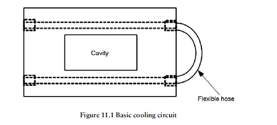
The most basic circuit, shown in Figure 11.1, consists of two drilled holes running parallel to the longest sides of a rectangular moulding. This is not a good design as the cooling effect will be greater adjacent to the cooling channels than it is on the other two sides of
the component. This inefficient design leads to over-long cooling cycles and frequently,loss of part quality.
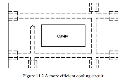
Figure 11.2 shows a more efficient circuit giving more uniform cooling around all four sides of the moulding.
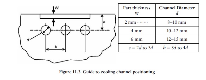
The location of channels around larger areas is important for efficient cooling. A guide to cooling channel positioning is shown in Figure 11.3. If the channels are too far apart, there is danger of an uneven thermal gradient developing between them. If the channels
are too close together, there is a danger that the thickness of steel between them may become too low. If they are too close to the cavity surface, an additional problem may occur with localised ‘over-cooling’, resulting in irregular temperature control.
Mould Temperature Control.
Some of the heat supplied to the material during the plasticising and Continue reading
Double Ejection.
Deep drawn box mouldings often have wall thicknesses that are too thin to eject on directly. Continue reading
Hybrid Ejection Systems
Many ejection systems require a high degree of ingenuity, on the part of the mould designer, to solve ejection problems. Several factors may combine together to create difficulties in designing suitable systems. These include the cavity form and geometry, the
material and the type of cavity construction. In practice, a mixture of methods may be used. Mechanical, pneumatic and hydraulic systems may be combined in difficult cases.
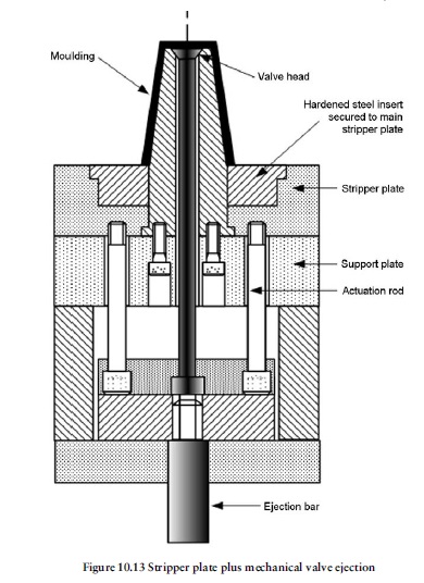
Figure 10.13 shows a stripper plate system with a direct mechanical valve ejector. This may also be combined with compressed air ejection if necessary.
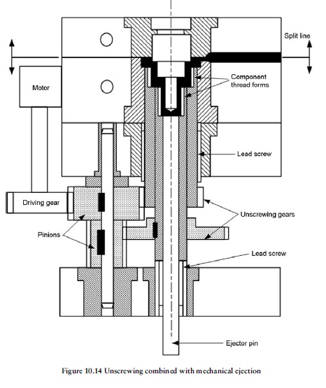
Figure 10.14 shows another typical mechanical–hydraulic–pneumatic system. In this case a threaded part is being moulded. A hydraulic or pneumatic motor drives the pinions during the unscrewing phase. After this has been completed, the part is ejected by means of a mechanically operated ejector pin.
In other cases, the unscrewing phase is often sufficient to push the part clear of the cavity with a final air blast is used to ensure complete clearance.
Ejection Assembly Actuation
The ejector pins, sleeves or stripper actuators, together with their retainer and backing plates, form the ejection assembly. Continue reading
How to calculate the Ejection Force
The basic SI unit of force is the newton, which has the symbol N. Continue reading
Stripper Plate and Valve Ejection.
Stripper Plate Ejection
Stripper plate systems are very effective and usually more Continue reading


You must be logged in to post a comment.