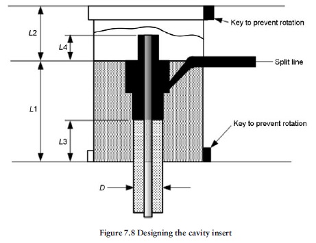
We can machine the impressions straight into a plate, but this has two disadvantages:
1. A plate that has cavities sunk directly into it may suffer form warping or distortion during the hardening process.
2. If a cavity suffers any damage during production, it can be very difficult to repair it.
It is therefore common practice to use cavity inserts to avoid these problems since:
(a) It is easier for the toolmaker to work on the inserts, as they are smaller.
(b) If any damage occurs it is much easier to replace an insert.
The diameter of the inserts should be large enough where possible to ensure that the whole of the sub gate form lies inside the insert as shown. This makes the spark machining of the sub gate easier and eliminates join lines that may prevent the gate exiting cleanly during ejection. As a rule of thumb, the following guidelines are suggested (see Figure 7.8). Further refinements come with experience.
The length of the lower insert L1 should be the depth of the part below the split line + 1.5–2 times the length of the sleeve ejector diameter for adequate sliding location L3.
The length of the upper insert L2 should be 1.5–2 times the height of the form in the insert L4.
Note that the lengths L1 and L2 automatically determine the plate thickness for the fixed half and ejection half of the tool. However, plates are only available in standard thicknesses from suppliers such as DME, DMS and Hasco. Therefore, the nearest standard plate sizes should be selected to determine final cavity depths.
