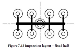
We have now reached the stage where we can determine the rest of the mould layout in plan view.The first stage is to lay out the impressions.
The view shown in Figure 7.12 is of the fixed half of the tool. This enables us to draw in the sprue bush and then arrange the cavity inserts around it. Note: the scale has been reduced for this view.
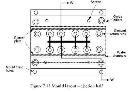
We can now switch to completing the layout by looking at the ejection half of the tool. Figure 7.13 completes the picture. First the waterways are included as previously determined. Then the limits of the ejector plate can be established just outside the cavity inserts. Next the return pins are drawn in, followed by the guide pillars and screws. Just outside the guide pillars, the outside of the main tool can now be established (based on standard plate sizes). The platen drawing will have to be consulted to determine the positions of the mould fixing holes. A flange is drawn on the outside of the tool to
accommodate these.

