It is also necessary to introduce cooling into cavity inserts wherever this is possible. On many jobs, cooling the cores without cooling the cavities can lead to nonuniform cooling of the component, resulting in lack of control.
With larger cavity inserts it may be possible to incorporate circular channel systems by using drilled holes systems like the angled hole or stepped hole designs. Alternatively, arrays of parallel straight holes may be used where the size and construction of the cavity
permits. In many cases, however, more complex arrangements are necessary owing to limitations in size or complexity of cavity construction.
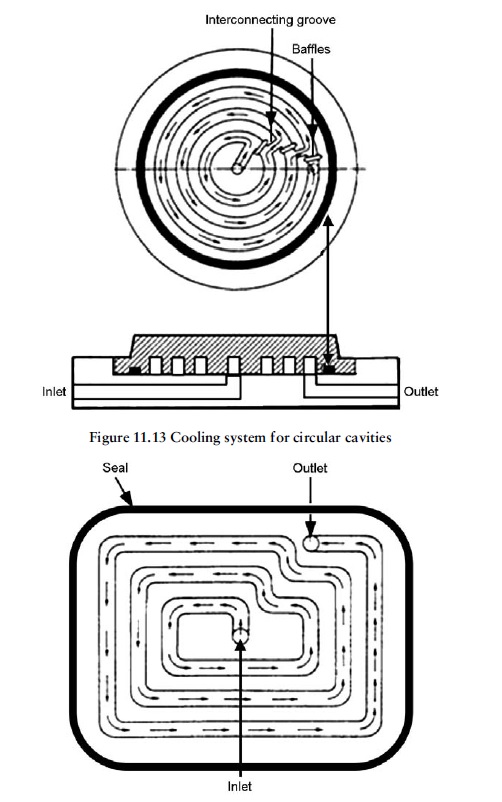
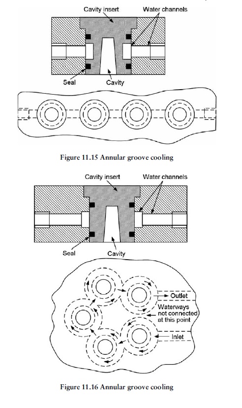
Depending on how the cavity has been designed, cooling may be introduced around or beneath the insert. Figures 11.13, 11.14, 11.15 and 11.16 illustrate different methods that are commonly used for cavity insert cooling.
In all these systems, O-rings or gaskets have to be used to prevent cooling fluid leaking from them. Careful attention has to be paid to sealing, as water leaks are quite common and can have disastrous consequences. Any water leaks inevitably tend to find their way
into the cavities, often resulting in rust damage.
As cavity inserts are usually situated deep inside the mould, the normal method of supplying cooling fluid to them is to machine channels from the outside of the mould, which also have to be sealed. An alternative is to use copper pipe with a BSP taper thread,
which passes through a clearance hole in the mould and is directly screwed and sealed into the insert.
As with most mechanical designs, the best design is the simplest one. Therefore, the design that uses the least complex construction and the least amount of sealing is to be preferred.

