Counter-sinking is often done to accommodate heads of flat head screws.However as can be seen from the figure, there is a sideways component of the thrust which could split the countersink due to the generated hoop stresses
Counter-boring is done to accomodate pan-head, fillister-head or round-head screws or other screws with flat-bottomed undersides.

- Counter-bored screws exert only force in the axial direction, thus operate mostly under compression, with no sideward component to the applied force vector. Such design is inherently more robust than counter-sinking.
Links: Article link.
Holes and Coring
Holes are easily produced in molded parts by core
pins which protrude into the mold cavity. Through
holes are easier to mold than blind holes, because the
core pin can be supported at both ends. Blind holes
formed by pins supported at only one end can be offcenter
due to deflection of the pin by the flow of
molten plastic into the cavity. Therefore, the depth of
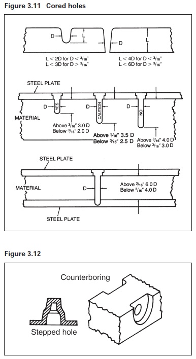
a blind hole is generally limited to twice the diameter
of the core pin. Design recommendations for cored
holes are shown in Figure 3.11. To obtain greater hole
depth, a stepped core pin may be used or a side wall
may be counterbored to reduce the length of an
unsupported core pin (see Figure 3.12).
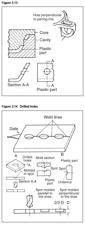
Holes with an axis which runs perpendicular to the
mold-opening direction require retractable core pins or
split tools. In some designs this can be avoided by
placing holes in walls perpendicular to the parting
line, using steps or extreme taper in the wall (see
Figure 3.13). Core pins should be polished and draft
added to improve ejection.
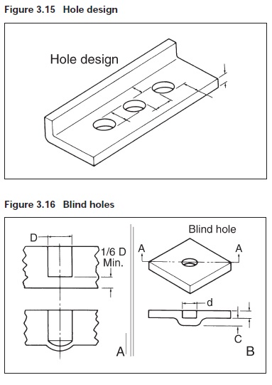
Where weld lines caused by flow of melt around core
pins is objectionable from strength or appearance
standpoint, holes may be spotted or partially cored to
facilitate subsequent drilling as shown in Figure 3.14.
The guide below, referring to Figure 3.15, will aid in
eliminating part cracking or tear out of the plastic parts.
d = diameter
b = d
c = d
D = d
t = thickness
For a blind hold, thickness of the bottom should be no
less than 1⁄6 the hole diameter in order to eliminate
bulging (see Figure 3.16 A). Figure 3.16 B shows a
better design in which the wall thickness is uniform
throughout and there are no sharp corners where stress
concentrations could develop.


