Radius
Sharp corners greatly increase the stress concentration.This high amount of stress concentration can often lead to failure of plastic parts.Sharp corners can come about in non-obvious places. Examples of this are a boss attached to a surface, or a strengthening rib. These corners need to be radiused just like all other corners. The stress concentration factor varies with radius, for a given thickness.
As can be seen from the above chart, the stress concentration factor is quite high for R/T values lesss than 0.5. For values of R/T over 0.5 the stress concentration factor gets lower.The stress concentration factor is a multiplier factor, it increases the stress.
- Actual Stress = Stress Concentration Factor K x Stress CalculatedThis is why it is recommended that inside radiuses be a minimum of 1 x thickness.
In addition to reducing stresses, fillet radiuses provide streamlined flow paths for the molten plastic resulting in easier fills.
Typically, at corners, the inside radius is 0.5 x material thickness and the outside radius is 1.5 x material thickness. A bigger radius should be used if part design will allow it.

SHARP CORNERS
Sharp corners greatly increase stress concentration, which, when high enough, can lead to part failure. Sharp corners often come about in non-obvious places, such as a boss attached to a surface, or a strengthening rib. The radius of sharp corners needs to be watched closely because the stress concentration factor varies with radius for a given thickness. As illustrated in the chart to the left, the stress concentration factor is high for R/T values less than 0.5, but for R/T values over 0.5 the concentration lowers. The stress concentration factor is a multiplier that greatly increases stress. It is recommended that an inside radius be a minimum of one times the thickness.
In addition to reducing stresses, the fillet radius provides a streamlined flow path for the molten plastic, resulting in an easier fill of the mold.
At corners, the suggested inside radius is 0.5 times the material thickness and the outside radius is 1.5 times the material thickness. A bigger radius should be used if part design allows.

https://www.solidconcepts.com/resources/design-guidelines/injection-molding-design-guidelines/
Sharp internal corners and notches are perhaps the
leading cause of failure of plastic parts. This is due to
the abrupt rise in stress at sharp corners and is a
function of the specific geometry of the part and the
sharpness of the corner or notch. The majority of
plastics are notch sensitive and the increased stress at
the notch, called the “Notch Effect,” results in crack
initiation. To assure that a specific part design is
within safe stress limits, stress concentration factors
can be computed for all corner areas. Formulas for
specific shapes can be found in reference books on
stress analysis. An example showing the stress concentration
factors involved at the corner of a cantilevered
beam is shown in Figure 3.07.
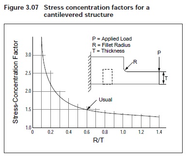
It is from this plot that the general rule for fillet size is
obtained : i.e., fillet radius should equal one-half the
wall thickness of the part. As can be seen in the plot,
very little further reduction in stress concentration is
ois obtained using a larger radius.
From a molding standpoint, smooth radii, rather than
sharp corners, provide streamlined mold flow paths
and result in easier ejection of parts. The radii also
give added life to the mold by reducing cavitation
in the metal. The minimum recommended radius
for corners is 0.020 in (0.508 mm) and is usually
permissible even where a sharp edge is required (see
Figure 3.08).

