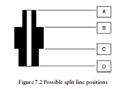
This is always a crucial stage in the mold design process.If we get this wrong the repercussions will be severe in production. In fact there are only two possible places where this component can be split: at B or C in Figure 7.2. If we tried to split the component at A or D it would be undercut in the tool and it could not de moulded in a two-plate tool because it could not be ejected from the cavity.
We could split the tool at position C as shown in Figure 7.3. If we were to select this position for the split line, this would work as the moulding will shrink away from the cavity walls and on to the pin that forms the central hole.
However, this is not the best method, especially from the point of view of accuracy and toolmaking, because the majority of the cavity form (X+Y) would be in the injection half or fixed half of the mould and it would be better if the majority of the form were in the
ejection side of the tool. It is desirable to have as much cavity form in the ejection half as possible because the majority of the toolmaking work will be on this side of the tool. This is because the ejector system is also in this half of the tool and it would be sensible to have as much of the form as possible to be machined in this half in the same operation. This minimises the matching up of cavity forms in the two separate halves of the tool. If we
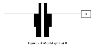
split the tool at B, we will have achieved this with X in the injection half and Y+Z in the ejection half.
This is a good procedure to follow in general as, apart from toolmaking considerations, the greater the amount of component in the ejection half; the more likely it will be that the component stays on this side of the tool when it opens. This is clearly essential, as the component must stay on the ejection half of the tool after it opens in order to be ejected. Therefore, we will split the tool at B as shown in Figure 7.4.


