The simplest method of supplying cooling fluid to the mould is to drill holes in the mould plates around the cavities. These should be of standard drill sizes and of sufficient diameter to permit an adequate flow of cooling fluid.
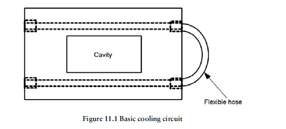
The most basic circuit, shown in Figure 11.1, consists of two drilled holes running parallel to the longest sides of a rectangular moulding. This is not a good design as the cooling effect will be greater adjacent to the cooling channels than it is on the other two sides of
the component. This inefficient design leads to over-long cooling cycles and frequently,loss of part quality.
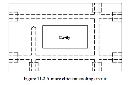
Figure 11.2 shows a more efficient circuit giving more uniform cooling around all four sides of the moulding.
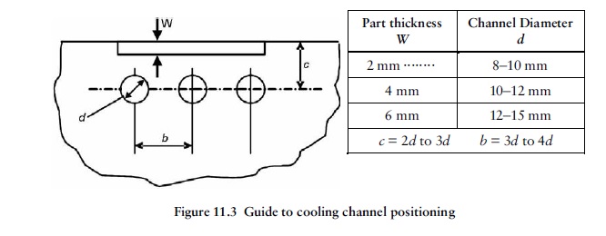
The location of channels around larger areas is important for efficient cooling. A guide to cooling channel positioning is shown in Figure 11.3. If the channels are too far apart, there is danger of an uneven thermal gradient developing between them. If the channels
are too close together, there is a danger that the thickness of steel between them may become too low. If they are too close to the cavity surface, an additional problem may occur with localised ‘over-cooling’, resulting in irregular temperature control.


