If the holding pressure is removed before the gate has frozen off, the compressed melt in the cavity will flow back through the gate into the runner system,causing the problems of sink marks and the formation of voids. In addition to maintaining holding pressure, it is
essential that a small cushion or volume of material is held in front of the screw at all times. This ensures that that there will be sufficient materials available for pressurising the cavities through the complete injection cycle.
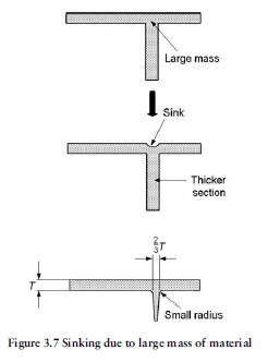
Figure 3.7 shows the classic problem at the junction of two sections of different thicknesses that creates a large mass of material, resulting in sinking. To avoid this, ribs and similar features should not be thicker than two-thirds of the main section of the moulding. Preferably they should also taper to a thinner section at the bottom, as shown.
Excessively thick sections are always prone to this problem but it may sometimes be disguised by introducing a surface texture on the affected area as shown in Figure 3.8. Figure 3.8(a) shows the original component; (b) shows a textured finish, which has reduced the effect; (c) shows a change to a lighter colour, which almost makes the sink disappear; and (d) shows a change of contour to a curved surface, which has reduced the problem a little. However, it is far better to avoid the problem completely by altering the part design where this is possible.
Figure 3.9 illustrates voids occurring where excessively thick sections exist in a moulding. Although moulding technique can help reduce this problem, it usually cannot cure it completely. Once again, the design of the part is not suitable for injection moulding,
where we require all sections to be reasonably uniform or reducing the farther away they are from the gate.


