Deep drawn box mouldings often have wall thicknesses that are too thin to eject on directly. The solution is usually to use a single large ejector, a series of ejectors or perhaps a valve ejector under the top of the part. Unfortunately, this leaves the moulding resting on top of the ejector pins, so another stage of ejection is needed to clear the parts. The usual solution is to use double ejection. This can be a mechanical system driven or supplemented by air or hydraulics. A typical solution for a cap component is shown in Figure 10.15.
In this design, phase 1 shows the mould tool closed. In phase 2 a hydraulic ejector pushes forward both ejector assemblies A and B together as a single unit to free the outer wall section so that the moulding may be able to deflect. Once this has occurred, the first-stage ejection assembly A hits a fixed stop and cannot move any further forward to complete phase 2. In phase 3 the second-stage ejector assembly B moves further forward, leaving the first stage behind, thus completely clearing the moulding from the cavity.
The key to the operation of this type of double ejection design is the module that connects the two ejector plate assemblies together. A spring-loaded collet ensures that the two systems move forward together as a single unit to complete the first stage. The lower
assembly then hits a mechanical stop, the collet disengages, and the upper assembly continues forward, completing the second stage.
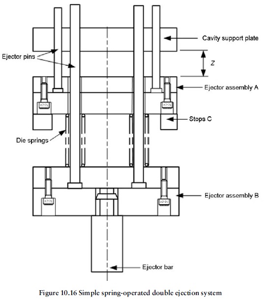
Figure 10.16 shows a very basic but nevertheless effective method of achieving double ejection for noncritical applications. After the tool opens, both ejector assemblies A and B move forward distance Z together as a single un il assembly A is forced to stop by the
cavity support plate above it. As the ejection stroke continues, the die springs compress, allowing assembly B to continue forward until they in turn hit the stops C.
Clearly the whole success of the operation depends on the stiffness of the die springs being selected to allow this to take place. To avoid premature fatigue of the die springs, they should not be allowed to become coil-bound when they are compressed for the second stage ejection: hence the need for the dead stops C.

