It is often desirable and sometimes essential to provide cooling inside core pins.In many cases core pins will get very hot if no cooling is incorporated in them, resulting in prolonged cooling cycles. In extreme cases, lack of cooling can prevent satisfactory
production, as the moulding remains too soft to eject for many minutes.
Several different methods are used for cooling cores and cavities depending on their size and construction:
- Baffle system
- Fountain system
- Angled hole
- Stepped hole
- Spiral cooling
- Heat rods
- Heat pipes
- Beryllium copper cores and cavities
Baffle System
This is a simple method of cooling smaller cores, although arrays of baffles may be used in larger cores. A hole is bored into the core and a strip of copper is inserted into it. It must be a good fit in the hole so that fluid does not leak past it. To ensure unrestricted flow, the cross-sectional area of the gap each side between the baffle and the hole must be numerically equal to at least half of the bore diameter. Figure 11.4 shows a typical multiple baffle system inside a large core. With a series circuit no more than four baffles should be interconnected to avoid an undesirable increase in fluid
temperature.

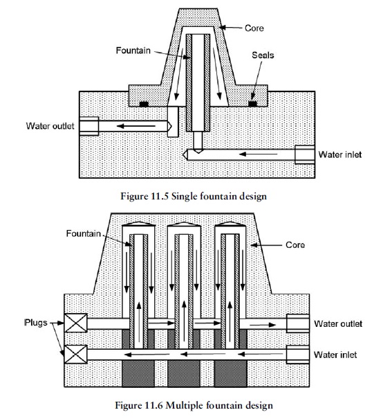
Fountain System.
Fountain designs are more efficient than baffle systems because the cooling circuitry is usually in parallel not series. This gives a more uniform temperature control over the entire moulding area. With this design a tube is fitted into the centre of a hole in the punch or core pin.
Fountain designs are not restricted to multiple-array use in a single large core but may also be used to cool core pins in individual cavities. Figures 11.5 and 11.6 show constructional details for a typical fountain design and the system used for an array in a larger punch.
Angled Hole Design
As the name implies, this method consists of drilling holes at angles in larger punches so that they intersect each other to create a path for the cooling fluid to flow through. The main difficulty with this method is that the drilled holes must intersect each other on a
full diameter. This becomes increasingly difficult to achieve as the length of the drilled holes increase, owing to the tendency of the drill to wander off course. In practice the length of the holes is restricted to a maximum of about 150 mm to ensure full diameter
intersection.
With this design, there is a danger that swarf from the drilling operation may be trapped at the intersections of the holes, thus restricting the flow of coolant through the core. It is good practice to check the waterways to make sure they are clear of any obstructions before running the tool in production.
Small-bore deep holes may be machined with EDM techniques. This is a more expensive option but is well worth the cost for installing cooling channels in smaller, more intricate cores. Figure 11.7 shows a typical angled drilled hole design used in larger cores and punches.

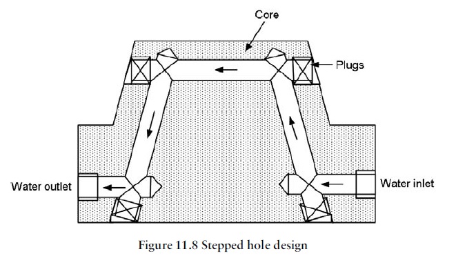
Stepped Hole Design
This is an easier system for toolmakers to make than the angled hole design, as it is not so difficult to match up the drilling. Where drilled holes break through into the punch surface they have to be plugged and then brazed or welded over. This witness is then ground away to match the punch form. A problem associated with this system is that owing to the injection pressure and continued cyclic expansion and
contraction, the plugs are sometimes prone to leak.
This system can cause problems where the job is of a critical appearance nature. A witness can often be seen on the moulding where the plugs are positioned, either in the form of a ring or sometimes a blush mark. The blush mark effect is due to a differential cooling effect through the plug to the moulding surface, which occurs if the plug is made from a different material from the core. To avoid this, the plug should be made from the same material as the core, usually alloy tool steel. This is obviously more expensive than using a standard bronze plug but may be justified on critical appearance parts. Figure 11.8 is typical of a stepped hole design, but more than one circuit may be used in a single punch where necessary.
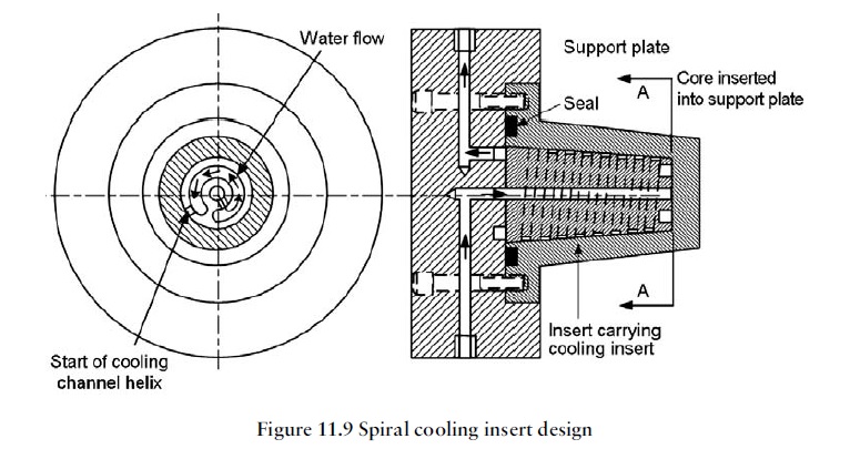
Spiral Cooling
For larger cylindrical cores above 50 mm diameter, spiral cooling systems provide more uniform and efficient cooling permitting quite good temperature control. A variety of different designs can be used depending on the sizes of the cores and the space available. The basic design uses a channel that is machined down the outside of a
centrally inserted tapered diameter and follows the path of a helix (Figure 11.9).
Seals have to be used to prevent leakage in this type of design. Where space permits, a double helix may be used to provide two cooling channels that run next to each other.
The single-channel and double-channel systems are very similar to a single-start and two start screw thread respectively. The remaining wall section of the core must also be thick enough to withstand the forces generated during injection of the polymer. Cooling channels must also be far enough away from the core surface to prevent excessive chilling of the polymer too quickly.
Heat Rod
For smaller punches and core pins it can be difficult to fit fountains or baffles. In these cases heat rods are often used. These consist of high thermal conductivity materials that are inserted into the core pin. The material most frequently used is copper, which is both
ductile and an excellent conductor of heat.
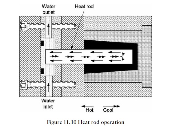
The principle of operation is that the copper conducts the heat away from the core pin into the path of a cooling fluid. It is important to ensure that there is intimate contact between the heat rod and the core pin for efficient heat transfer. The ductility of copper is very useful in this respect as it can be lightly tapped into the core pin and will spread out to give the good contact as required. Figure 11.10 illustrates the principle of the use of heat rods.
Heat Pipe
Heat pipes are also used for cooling small core pins. They act as heat exchangers just like a heat rod but operate on a different principle. A heat pipe consists of a copper tube sealed at both ends with a fine ‘wick’ running along the length of the inside wall of the tube. The tube is filled either with water or with a low-boiling-point alcohol. The liquid vaporises as it picks up heat from the moulding and travels to the other, cooler, end of the tube that is placed in the flow of a cooling fluid. The vapour at the cool end of the tube condenses back into fluid and is drawn back up to the hot end by capillary action.
Figure 11.11 illustrates the principle. Once again, the efficiency of heat transfer depends on the contact between the outside of the heat pipe and the inner wall of the core pin. In order to assist in this respect, a heat transfer paste is normally spread over the heat pipe before it is inserted into the core pin.
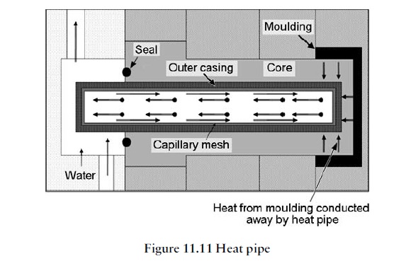
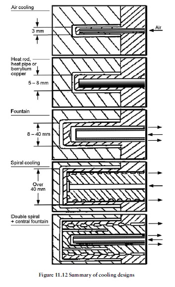
Figure 11.12 gives a summary of the types of core cooling that can be used with increasing core diameters.

You must be logged in to post a comment.